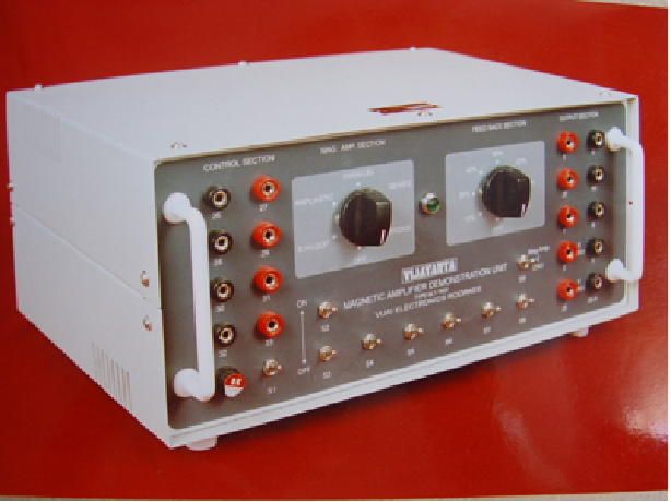
This is a very versatile unit which can be used for performing different experiments just by means of selector switches. All the control characteristics of basic transductors and Magnetic amplifier can be studied. The following gives a list of experiments that can be performed with this demo unit
SPECIFICATIONS:
INPUT SIGNAL :
-
Control Signals : Maximum 50, mAmp DC through control winding for series and parallel mag. Amp. connection and Max. Power 1080, VA.
-
AC Input in the load circuit 230 Volt, 6 Amps.
OUTPUT :
-
Maximum Power 1, KVA D.C..
-
Output Voltage can be varied upto 200 Volt D.C.
-
Load current can be upto 5, Amps. D.C
UTILITY :
-
Tto demonstrated all the control characteristics of the different basic magnetic amplifier circuits.
-
Unit can be used to control the speed of a 1, HP D.C. motor from 10% to 100% rated speed.
-
Unit can be used as a constant current device, between 0.5 Amp. to 3 Amp., smoothly variable for 0 – 200 Volt load voltage.
-
Unit can be used as a D.C. Voltage stabilizer. 50 – 200 Volts output smoothly variable upto a load of 5 Amp. D.C. within ± 2% stabilization at 200 Volts.
AMPLIFIER GAIN :
Approximately : 10,000.00
LIST OF EXPERIMENTS :
1. Study of B – H loop of the core material used on a C.R.O.
2. Magnetization characteristics of the gate winding of the saturable reactor.
3. Control characteristics of a series Transducer unit.
4. Series Magnetic Amplifier as a constant current source.
5. Control characteristics of a parallel Transducer unit non – polarized control characteristics.
6. Constant current property of parallel transducer unit.
7. Control characteristics of amplistat circuit on Autoexcited Magnetic Amplifier polarized control characteristics.
8. Control characteristics of a bridge ampliastat circuit for D.C. Load.9. Transfer characteristics of a series magnetic amplifier with external feed back a series self – excited magnetic amplifier unit with :
(a) 40% Feed – Back.
(b) 80% Feed – Back.
10. Bistable magnetic amplifier circuit with series self excited transducers – their switching operation.
11. Transfer characteristics of a parallel magnetic amplifier with external feed back a parallel self – excited Transducer with :
(a) 40% Feed – Back.
(b)80% Feed – Back.
12. Bistable operation of a parallel self saturating Magnetic Amplifier with 120% Feed – Back.
13. Bistable operation of an amplistat circuit with 40% of external feed – back.
14. Bistable operation of a bridge amplistat circuit with 40% of external feed – back.
15. Constant current D.C. drives speed torque characteristics of a D.C. Motor, the armature of which is supplied from a constant current source – their application is coiler drives.
16. Speed control of a D.C. Motor by magnetic control devices :
(a) Open loop system.
(b) Closed loop system – smooth speed regulation from about 20% to 100% of the rated speed and study of speed stabilization.
17. Constant Voltage D.C. stabilizer circuit study :
(a) An open loop.
(b) An closed loop – smooth output voltage variation from about 10% to 100% of the output voltage and study of voltage stabilization.
MODEL: M – 1 – 1600 A.
Same as above but D.C. output handling Capacity is 250, VA instead of 1, KVA
Note: There may be any change in specification due to continuous R & D without notice.
.png)