DESCRIPTION OF INSTRUMENT :
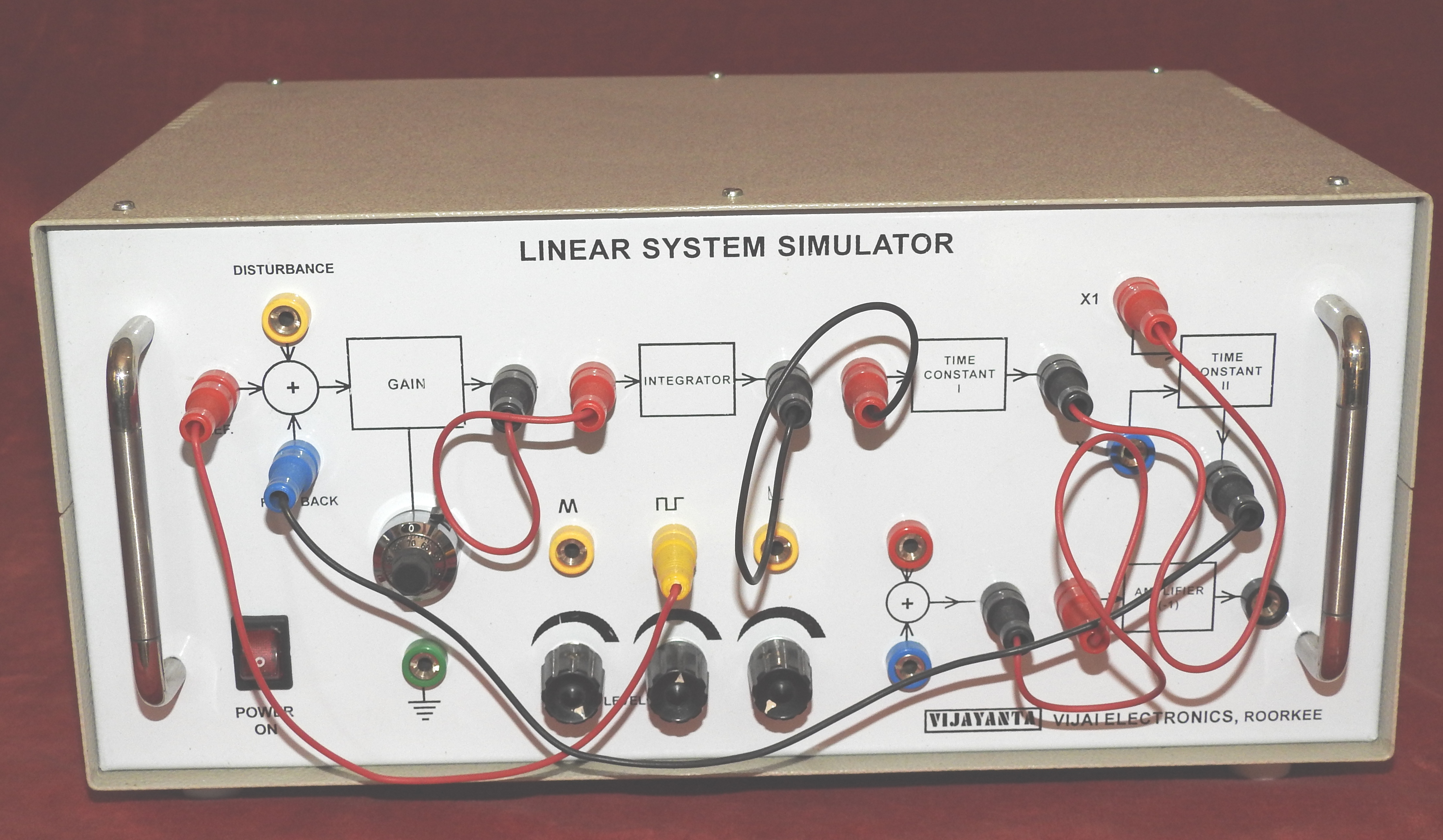
The linear system simulator set–up is designed to study the transient response of a linear system. Simple block diagram approach is used to system configuration. Disturbance points etc. a description is given below :
SIGNAL SOURCES :
There are three built-in sources in this unit.
- Frequency : 40 – 90 Hz (Variable)
- Square Wave : p – p amplitude 0 – 2 Volts
- Triangular Wave : p – p amplitude 0 – 2 Volts
- Trigger : ± 5 Volts (approximate)
FEATURES :
-
This unit is inside a metallic cabinet with front panel block diagram.
-
All the necessary switches, potentiometer and test points are on the front panel.
-
All the waveforms can be measured on a C.R.O.
-
Simulated First, Second and Third order system of Type – 0 and Type – 1.
-
Calibrated Variable gain amplifier of resolution 1 : 1000.
-
Builtin Signal source, Square wave and triangular wave with 45 – 90 Hz Frequency and 0 – 2.5 amplitude.
-
Provision for disturbance inputs.
-
Builtin Regulated Power Supply : 230 Volt, ± 10%, 50 Hz mains operated.
-
Detailed literature and patch cords.
-
Weight : 3 Kg Approximately
-
Dimension : 250mm × 350mm × 150mm
OBJECT:
To study the time response of various simulated linear systems.
1. Open Loop Response :
- Error Detector Cum Variable Gain
- Disturbance
- Amplifier
- Integrator
- Time Constants
2. Closed Loop Response :
- First Order System
- Second Order System
- Third Order System
ACCESSORIES REQUIRED :
- A general purpose Dual Trace, Oscilloscope.
Note: There may be any change in specification due to continuous R & D without notice.
Click below to view catalogue
.png)