The system set up is made up of synchro transmitter and synchro receiver on a single rigid base provided with suitable switches and anodized angular plates. The system also contains a step down transformer for providing excitation to the rotors.
A synchro is an electromagnetic transducer commonly used to convert an angular position of a shaft into an electric single.
The basic synchro is usually called a synchro transmitter. Construction is similar to that of a three phase alternator. The sator (stationery member) is of limited silicon steel and is slotted accommodate a balanced three phase winding which is usually to connectric coil type (three identical coils are placed in the stator with their axis 120 degree apart).
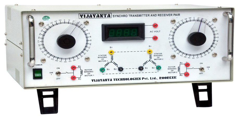
The input angular displacement dial display on the front panel for show the angular movement. The output angular displacement dial display on the front panel for show the angular movement. The rotor terminals (R1 & R2) and three stator terminals (S1, S2 & S3) are brought out on the front panel for both the synchro motors. One digital panel meter measurement the AC voltages (0-200 Volt AC) i.e. for taking The readings of stator & rotor voltages of motors. Power Supply : 230 Volt, 10%, 50 Hz.
The classical synchro systems consists of two units :
-
Synchro Transmitter (Tx)
-
Synchro Receiver (Tr)
EXPERIMENTS :
Study of synchro motor separately for rotor & stator output characteristics. Study of synchro motors as transmitter & receiver pair as error detector.
Note: There may be any change in specification due to continuous R & D without notice.
Click below to view catalogue
.png)