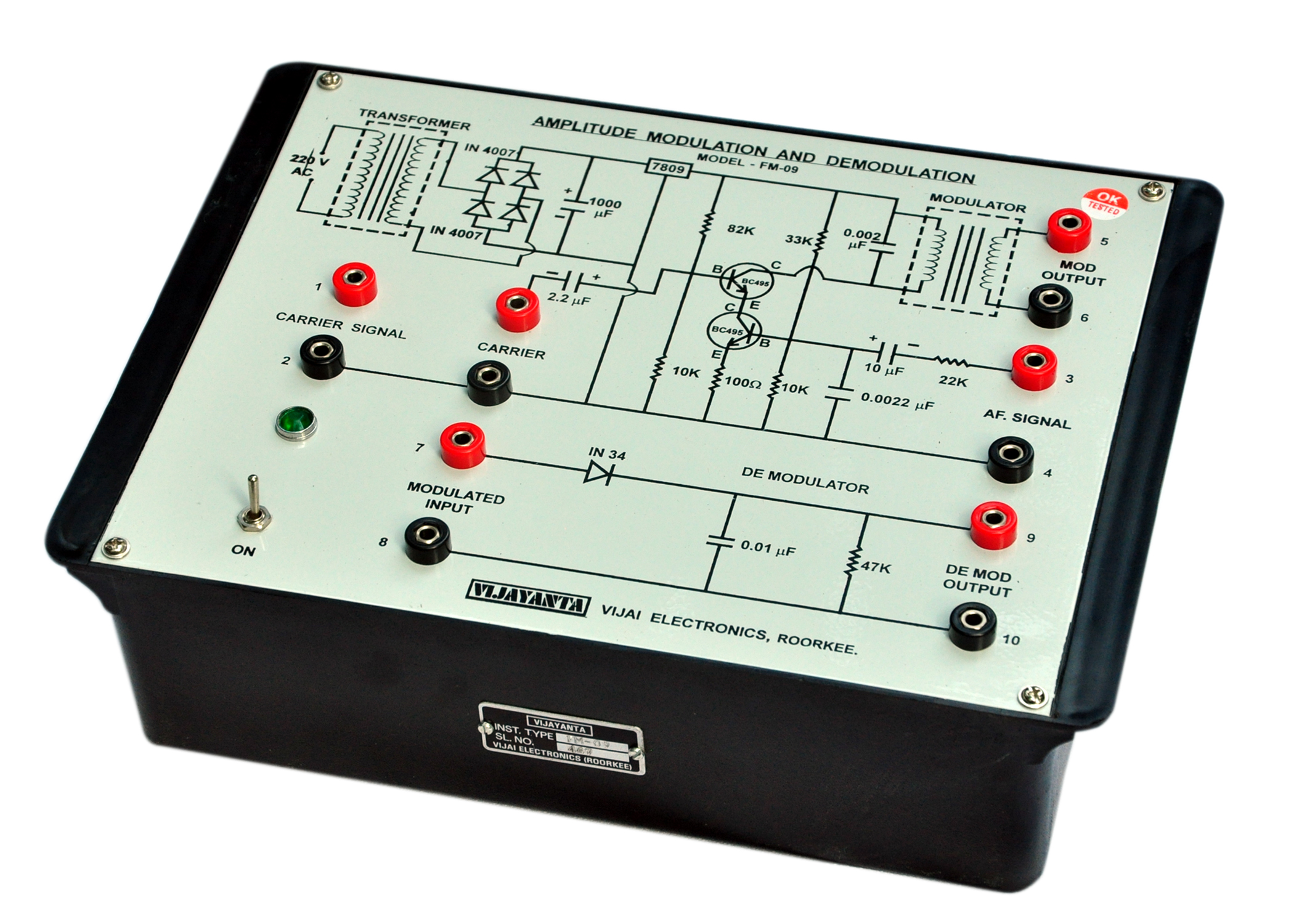
The set – up consists of modulating and demodulating circuits. It is provided with a fixed frequency (70 KHz) Oscillator, which may be used for carrier frequency. This eliminate the need of a R.F. Oscillator. The carrier signal may be given from any other oscillator also if the change in carrier frequency is desired. Since the circuit is designed for comparatively low frequency (70 KHz to 150 KHz) carrier signal, the usual A.F. Frequency Oscilloscope is good enough.
The experimental set – up have been laid – down on a bakelite board with an aim of providing an easy understanding to the students. All components are well spread out for clarity and easy repairs / replacement. The set – up is provided with a booklet, which contains it detailed theory of operation, description, specifications, suggestions and discussion on the various experiments that may be performed with it.
THE FOLLOWING STUDIES CAN BE CARIED OUT WITH THIS SET–UP:
-
Carrier Signal Testing
-
Variation of Modulated wave with the modulation signal
-
Study of detector circuit.
OTHER APPARATUS REQUIRED :
-
A. F. Oscillator, Model – 712.
-
A General purpose C.R.O., Model – 201. (“Scientech” make).
Note: There may be any change in specification due to continuous R & D without notice.
Click below to view catalogue
.png)