Resistance temperature detectors are primary electrical transducer enabling measurement of temperature changes in terms of resistance changes. The resistive element is usually made of a solid material, a metal, metallic alloy or a semiconductor compound. The Resistivity of metal increases with temperature, while that of semiconductors and insulators generally decreases. Wire wound elements employ considerable length of wire, and if free to expand, the length also increases with increase in temperature. Hence as temperature changes, the change in resistance will be due to changes in both length and Resistivity. Materials used for resistance thermometers have temperature. Coefficient of Resistivity much larger than the coefficient of thermal expansion.
- Weight : 2 Kg. Approximately
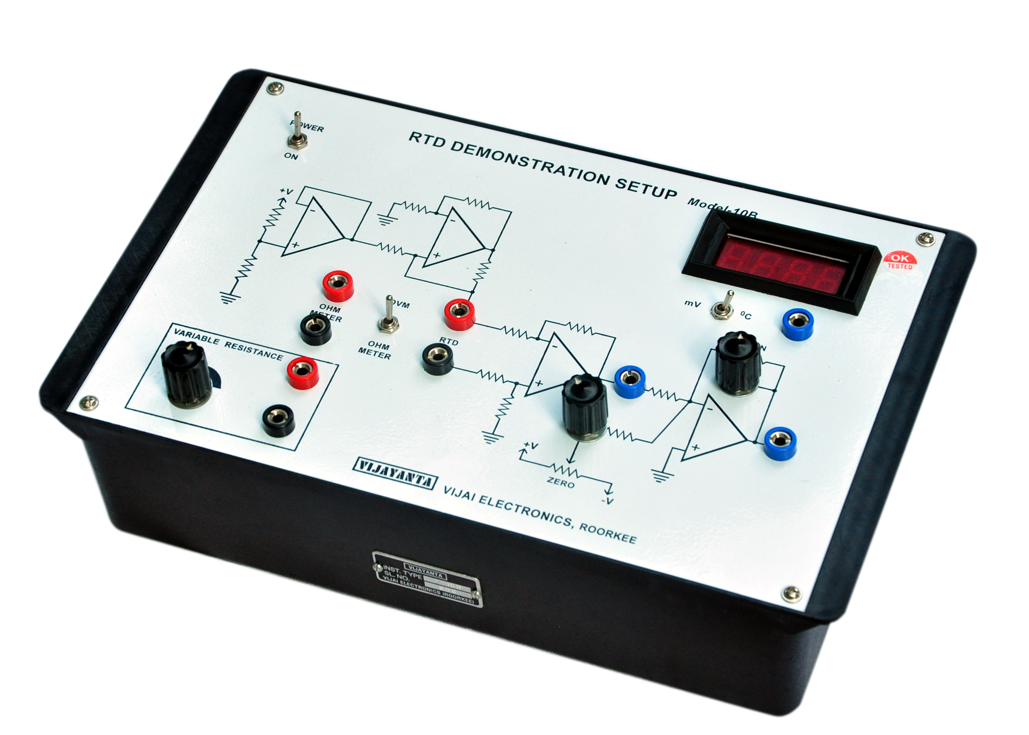
- Dimension : 195mm × 315mm × 75mm
THE SET–UP CONSISTS OF :
(a) R.T.D. (Resistance Temperature Detector) : PT – 100.
(b) DC Amplifier.
** For amplification of signal.
** Gain and Null adjustment facility on panel.
** Input, Output termination of panel.
(c) 3 ½ digit Digital Panel Meter for measuring of temperature.
(d) Power supply.
** Builtin over load and short circuit proof + 15 Volt and + 5 Volt D.C. supply for Amplifier and D.C. Amplifier and Digital Panel Meter.
** Input : 230, Volt, 50 Hz.
(d) Variable Potentiometer for Calibration.
EXPERIMENTS CAN BE PERFORMED :
(a) Characteristics of R. T. D. between :
** Resistance Vs temperature.
** Time Vs. Temperature.
Note : There may be any change in specification due to continuous R & D without notice.
Click below to view catalogue
.png)