Four Probe Set-up for Measuring the Resistivity of Very Low to Highly Resistivity Samples at Different Temperature upto 200°C with PID Controlled oven (Research Model)

DESCRIPTION :
The Four Probe Method is one of the standard and most widely used method for the measurement of resistivity. In its useful form, the four probes are collinear. The error due to contact resistance, which is significant in the electrical measurement on semiconductors, is avoided by the use of two extra contacts (probes) between the current contacts. In this arrangement the contact resistance may all be high compare to the sample resistance, but as long as the resistance of the sample and contact resistance's are small compared with the effective resistance of the voltage measuring device (potentiometer, electrometer or electronic voltmeter), the measured value will remain unaffected. Because of pressure contacts, the arrangement is also specially useful for quick measurement on different samples or sampling different parts of the sample.
DESCRIPTION OF THE EXPERIMENTAL SET-UP
1. Probes Arrangement
It has four individually spring loaded probes. The probes are collinear and equally spaced. The probes are mounted in a teflon bush, which ensure a good electrical insulation between the probes. A Teflon spacer near the tips is also provided to keep the probes at equal distance. The probe arrangement is mounted in a suitable stand, which also holds the sample plate and RTD sensor. This stand also serves as the lid of PID Controlled Oven. Proper leads are provided for the current and voltage measurement.
2. PID Controlled Oven, Model PID-TZ
The unit is a high quality PID controller wherein the temperatures can be set and controlled easily. The P, I and D parameters are factory set for immediate use however the user may adjust these for specific applications as well as auto-tune the oven whenever required. The steps for these are given in the user manual. Although the controller may be used either for our small oven, up to 200°C or a larger oven up to 600°C, however, in the present setup only small oven is to be used. The controller uses thermocouple as temperature sensor.
SPECIFICATIONS OF THE OVEN CONTROLLER
The controller is designed around Autonics Temperature Controller Model TZN4S. Although this is a very versatile piece of equipment, below is a summary of the specifications that are relevant to the present application. a reasonable level (P = 1.8; I = 300; D = 80) for immediate operation of the unit.
-
Temperature Range : Ambient to 200°C
-
Display Accuracy : ±0.3°C
-
Setting Type : Front push buttons
-
Control Method : PID, PIDF, PIDS
-
Measurement Accuracy : ±0.5°C (typical)
-
Oven : Specially designed for Four Probe Set-up
-
Sensor : Thermocouple (Chromel - Alumel)
-
Display : 7 segment LED, two rows
-
Values : Process Value, PV and Set Value, SV
-
Power : 150W
3. Constant Current Source
a) Constant Current Source, Model : CCS-01
(for low resistivity to medium resistivity samples)
It is an IC regulated current generator to provide a constant current to the outer probes irrespective of the changing resistance of the sample due to change in temperatures. The basic scheme is to use the feedback principle to limit the load current of the supply to preset maximum value. Variations in the current are achieved by a potentiometer included for that purpose. The supply is a highly regulated and practically ripples free d.c. source. The constant current source is suitable for the resistivity measurement of thin films of metals/ alloys and semiconductors like germanium.
SPECIFICATION :
-
Open Circuit Voltage : 10 V
-
Current Range : 0-20mA, 0-200mA
-
Resolution : 10μA
-
Accuracy : ± 0.25% of the reading ± 1 digit
-
Display : 3½ digit, 7 segment LED with auto polarity and decimal indication
-
Line Regulation : 0.05% for 10% changes
-
Load Regulation : 0.03% for 0 to full load
b) Low Current Source, Model : LCS-02
(for high resistivity samples)
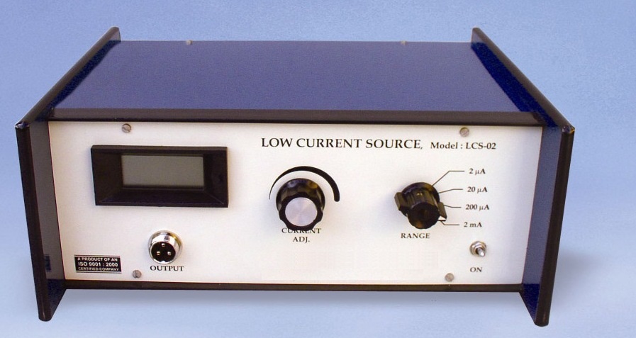
Low Constant Current Sources are needed, when the sample resistance, is large. As in the case of silicon wafers or high resistivity film deposits. Large resistance makes the measurement prone to pickups from the mains. This problem is reduced to very low level by using the battery instead of mains. Since the current requirement is very small, the batteries should have a reasonably long life. An internal voltage reference of 2.5 volt ensures reliable operation even when the batter voltage falls. A ten turn potentiometer makes the current adjustment very easy.
-
Open Circuit Voltage : 15V
-
Current Range : 0-2μA, 0-20μA, 0-200μA & 0-2mA
-
Minimum : 1nA at 0-2μA range
-
Accuracy : ± 0.25% of the reading ± 1 digit
-
Display : 3½ digit, 7 segment LCD with auto polarity and decimal indication
-
Load Regulation : 0.05% for 0 to full load
-
Power : 2 x 9V batteries
4. D.C. Micro voltmeter
Specifications as per datasheet in the catalogue
The experimental set-up is complete in all respect
NOTE: There may be any change in specification due to continuous R & D without notice.
Click below to view catalogue
.png)